|
ANIMAL SLIDES:
<Researchers><Test Data> <Equipment> |
|
|
|
DEVELOPMENT |
|
p3 |
|
<Previous>
<Full
size>
<Next>
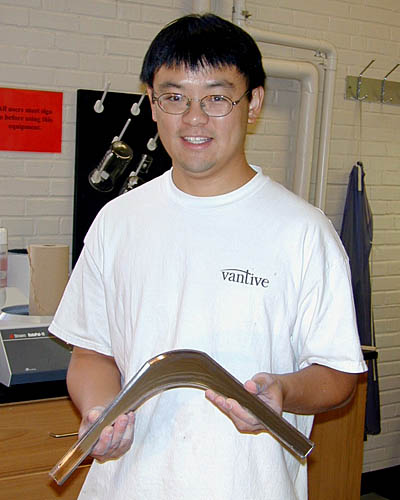
An Auburn University Ph.D. student in material science engineering assisted in polishing the interior of the flight tube (one half shown)
|
|
|
|
1
<Previous>
<Full
size>
<Next>
Early stages of development in ANIMAL
|
|
2 |
|
<Previous>
<Full
size>
<Next>
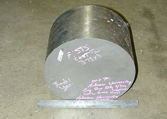
A round of cold-rolled mild steel was used for
machining the pole pieces of the electromagnet.
|
|
3 |
|
<Previous>
<Full
size>
<Next>
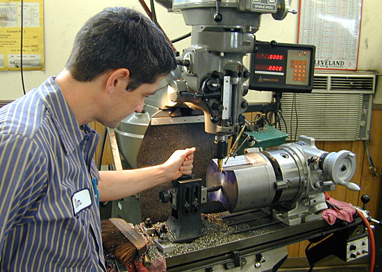
Auburn university machinist fabricating the pole
pieces of the electromagnet
|
|
4 |
|
<Previous>
<Full
size>
<Next>
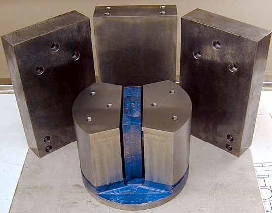
Frame (three pieces) and pole pieces of the
electromagnet following machining
|
|
5 |
<Previous>
<Full
size>
<Next>
This is a test text: Auburn Noble Isotope Mass Analysis Laboratory
Department of Geology and Geography
Auburn Noble Isotope Mass Analysis Laboratory Department of Geology
and Geography
|
|
6 |
|
<Previous>
<Full
size>
<Next>
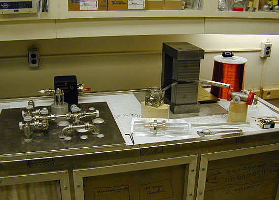
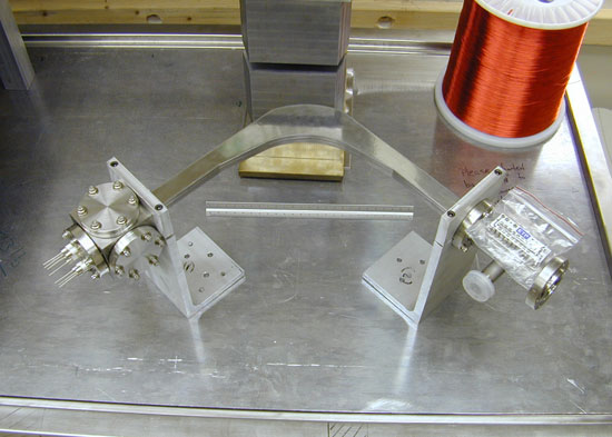
Early development and testing of the placement
for the source, flight tube, detector (note ETP multiplier) and
electromagnet. The fine wire, at right, was used in winding the
secondary electromagnet coils (for fine adjustment and computer
control).
|
|
7 |
|
<Previous>
<Full
size>
<Next>
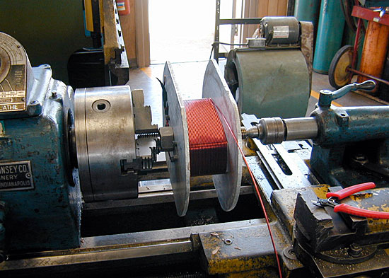
Winding a main coil for coarse control of the
electromagnet
|
|
8 |
|
<Previous>
<Full
size>
<Next>
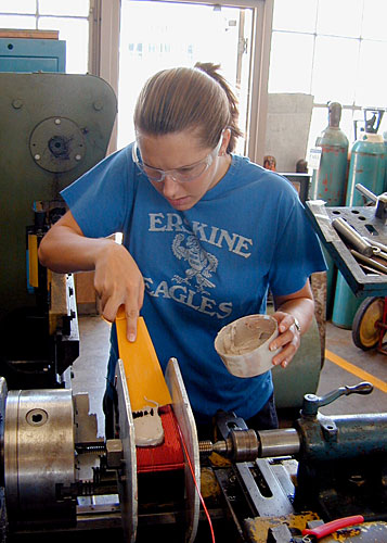
AU Geology graduate student Sarah Lavallee
winding a coil for the main (coarse) magnet control, in the Auburn
University Central Machine Shop
|
|
p1 |
|
<Previous>
<Full
size>
<Next>
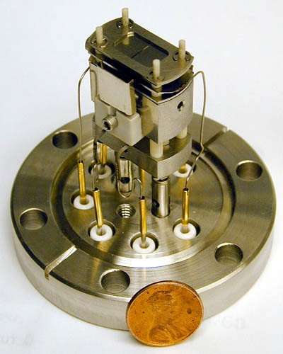
View of the electron-impact ion source, based on
Wallington (1971; after Nier, 1947). The source was designed to fit
conveniently within a 2.75" cube, and is mounted on a 2.75"
feedthrough flange
|
|
p2 |
|
<Previous>
<Full
size>
<Next>
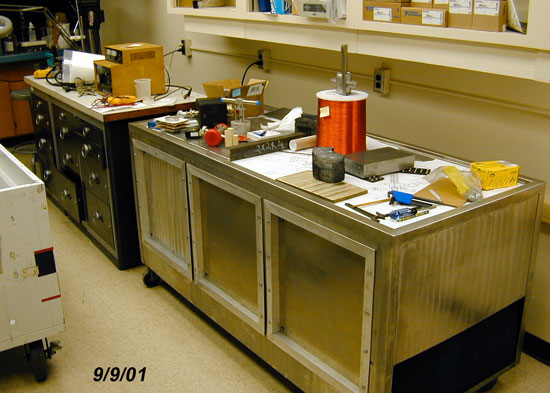
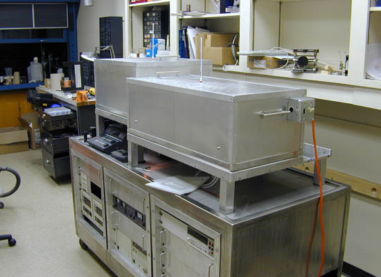
The table design and equipment layout permits the
extraction line and mass spectrometer to be baked independently at
temperatures up to 350 °C.
|
|
9 |
<Previous>
<Full
size>
<Next>
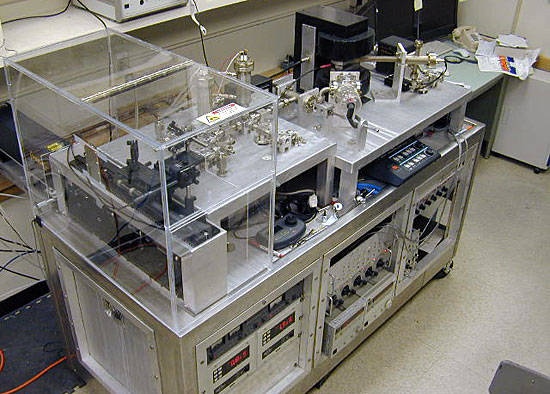
The complete system.
|
|
Top of Page |
; if (myWindow.focus) %7bmyWindow.focus(); %7d)
; if (myWindow.focus) %7bmyWindow.focus(); %7d)
; if (myWindow.focus) %7bmyWindow.focus(); %7d)
; if (myWindow.focus) %7bmyWindow.focus(); %7d)
; if (myWindow.focus) %7bmyWindow.focus(); %7d)
; if (myWindow.focus) %7bmyWindow.focus(); %7d)
; if (myWindow.focus) %7bmyWindow.focus(); %7d)
; if (myWindow.focus) %7bmyWindow.focus(); %7d)
; if (myWindow.focus) %7bmyWindow.focus(); %7d)
; if (myWindow.focus) %7bmyWindow.focus(); %7d)
; if (myWindow.focus) %7bmyWindow.focus(); %7d)
; if (myWindow.focus) %7bmyWindow.focus(); %7d)