|
ANIMAL SLIDES:
<Researchers><Development><Test Data> |
|
|
|
EQUIPMENT |
|
eq1 |
|
<Previous>
<Full
size>
<Next>
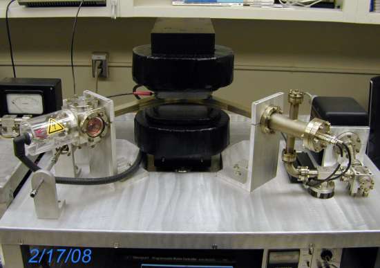
The mass spectrometer for ANIMAL is a 10-cm, 90° sector instrument with second order focusing (after Cross, 1951). The spectrometer has a single electron multiplier detector (ETP discrete dynode type), housed in a standard reducing cross (right). The source is based on a standard 2.75" cube. Note that there are two pairs of coils for the electromagnet-analyzer, and each is controlled with a 12-bit controller. The larger set of coils is kept in constant-current mode sufficient for a field of ~ 3100 Gauss (sufficient to being mass 35 to the detector, when operating at 2 kV). The smaller set of coils is under computer control, and when fully energized can increase the field to ~ 3500 Gauss (sufficient for ~ m/e=40.5 @ 2 kV). The total spectrometer volume (including an appendage getter-pump) is about 400 cc.
|
|
eq2 |
|
<Previous>
<Full
size>
<Next>
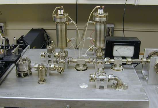
The extraction line has a volume of about 400 cc.
An air pipette (with pneumatic valves) and a turbo pump connect to
the extraction line underneath the table.
|
|
eq3 |
|
<Previous>
<Full
size>
<Next>
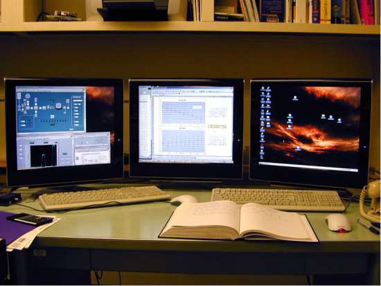
The operation of the laser system, extraction line, and analysis are fully automated, through a Labview program.
|
|
1 |
|
<Previous>
<Full
size>
<Next>
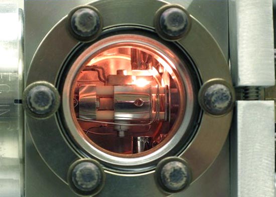
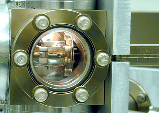
View of the Nier-type electron impact source
(after Wallington) and filament through a Pyrex window on the source
block (a standard 2.75” UHV cube). The source is spring-loaded, and
is guided with pins to rest on a plate to the right. Note the
external source magnet housings above and below the source.
|
|
2 |
|
<Previous>
<Full
size>
<Next>
A
second view of the ion source, with the beginning of the flight tube
at the right
|
|
3 |
|
<Previous>
<Full
size>
<Next>
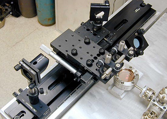
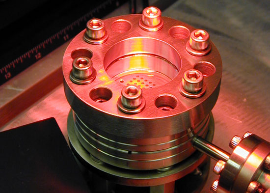
Early development and testing of the ‘flying
optic’ design for the laser sample chamber. The laser beam (from a
He-Ne steering laser in this case) comes from below the table
through a hole in the rail (to the left) and is directed down into
the sample chamber.
|
|
4 |
|
<Previous>
<Full
size>
<Next>
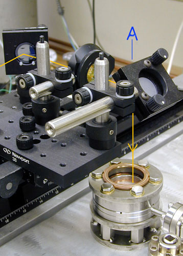
View of the optical path for the laser at a later stage of lab
development
|
|
5 |
|
<Previous>
<Full
size>
<Next>
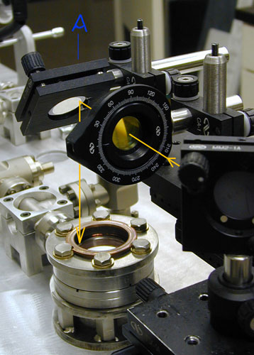
View of the optical path for the laser at a later
stage of lab development.
|
|
6 |
|
<Previous>
<Full
size>
<Next>
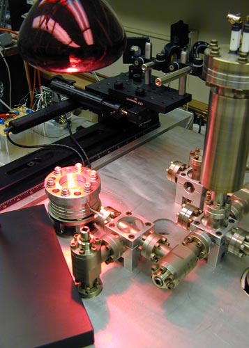
Heating and sample chamber bakeout to ~ 150 C
with an IR heat lamp.
|
|
7 |
<Previous>
<Full
size>
<Next>
Heating and sample chamber bakeout to ~ 150 C
with an IR heat lamp.
|
|
8 |
|
Top of Page |
; if (myWindow.focus) %7bmyWindow.focus(); %7d)
; if (myWindow.focus) %7bmyWindow.focus(); %7d)
; if (myWindow.focus) %7bmyWindow.focus(); %7d)
; if (myWindow.focus) %7bmyWindow.focus(); %7d)
; if (myWindow.focus) %7bmyWindow.focus(); %7d)
; if (myWindow.focus) %7bmyWindow.focus(); %7d)
; if (myWindow.focus) %7bmyWindow.focus(); %7d)
; if (myWindow.focus) %7bmyWindow.focus(); %7d)
; if (myWindow.focus) %7bmyWindow.focus(); %7d)
; if (myWindow.focus) %7bmyWindow.focus(); %7d)